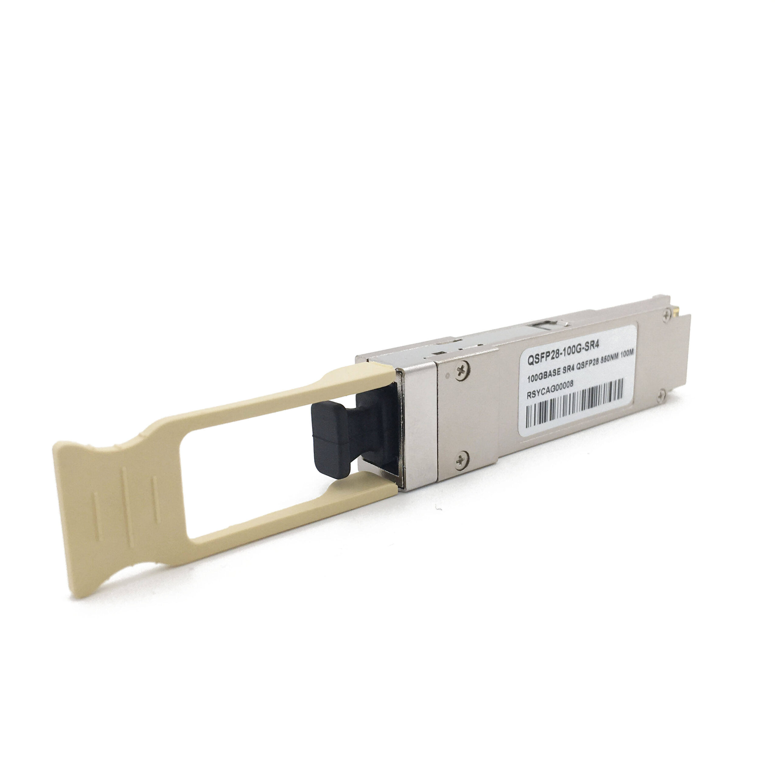
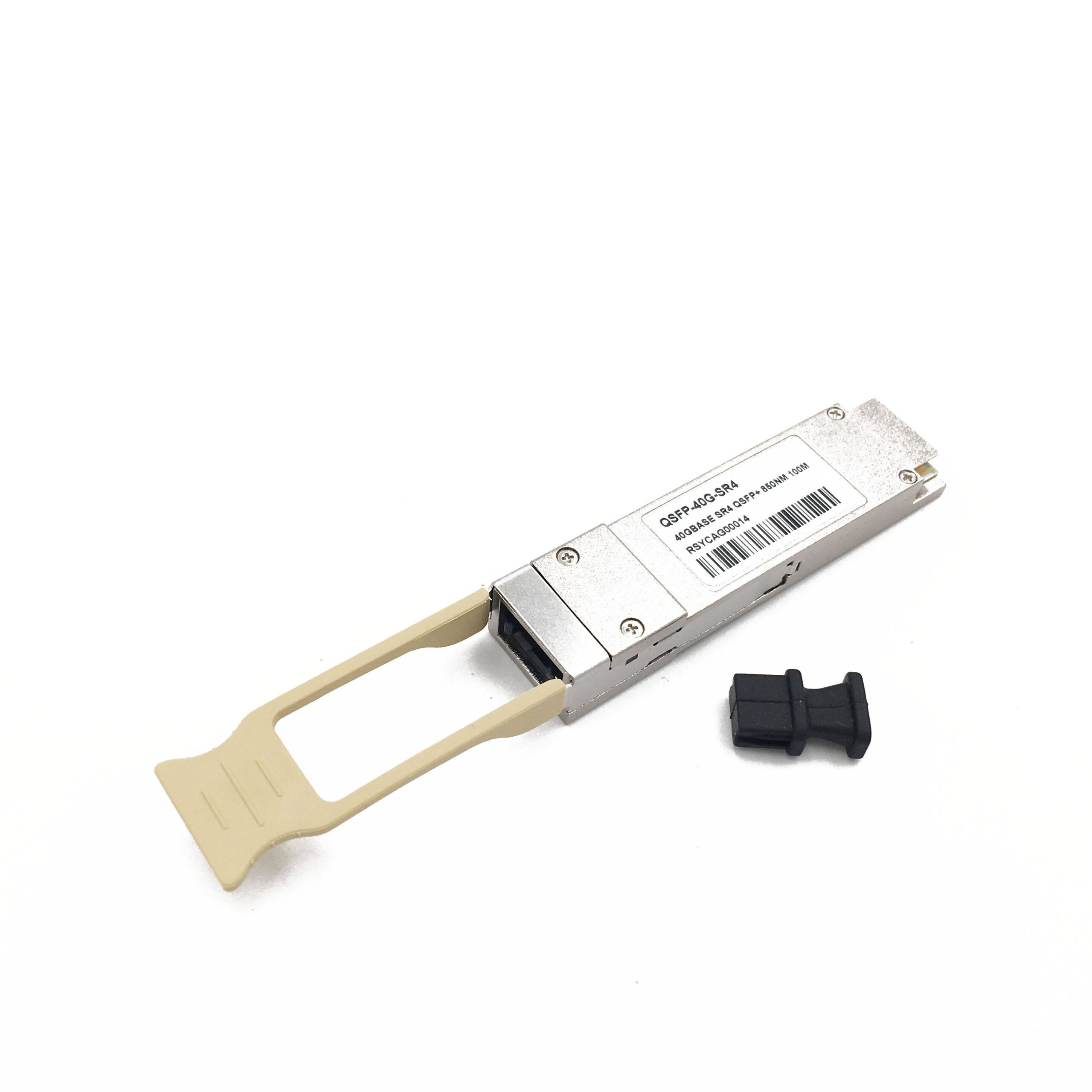
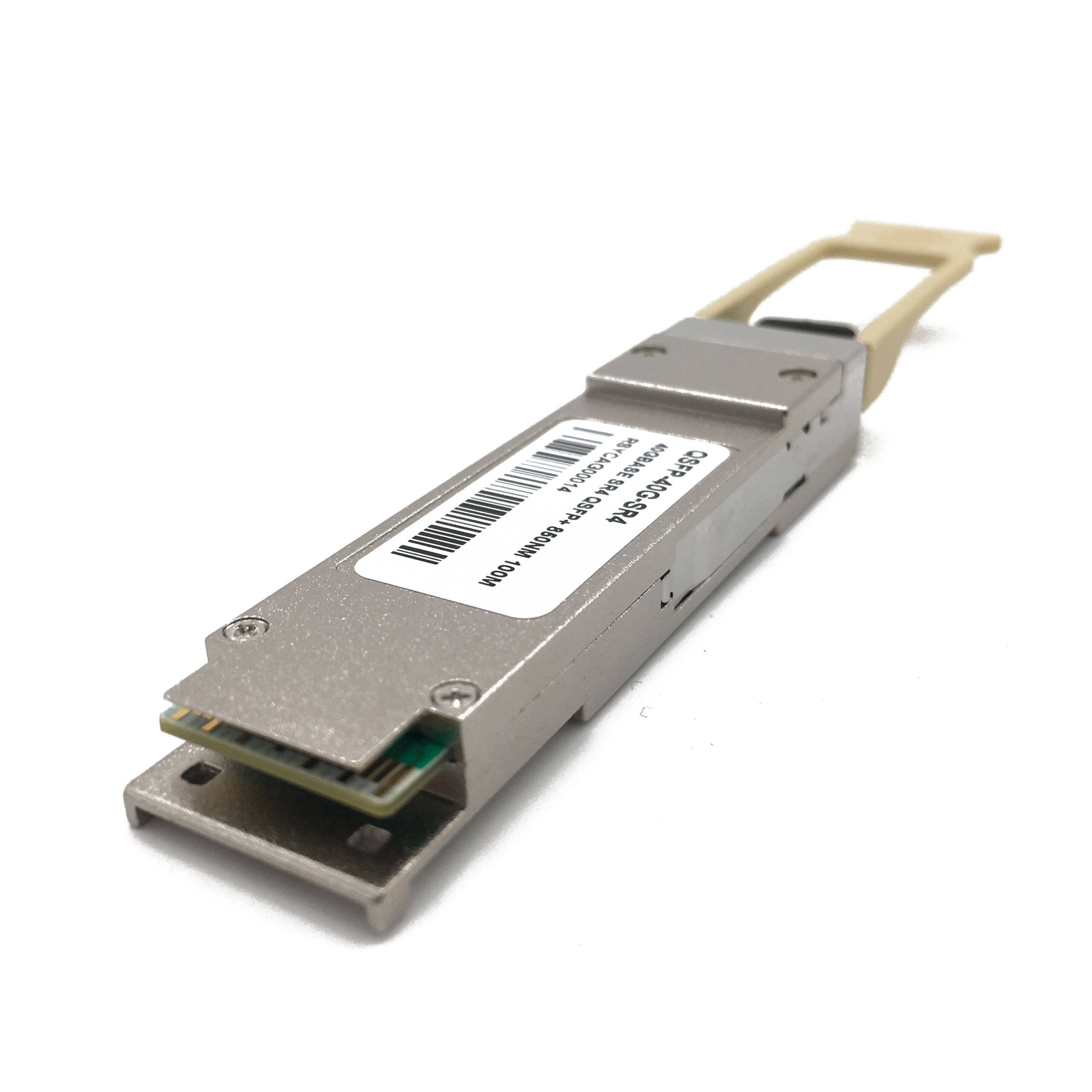
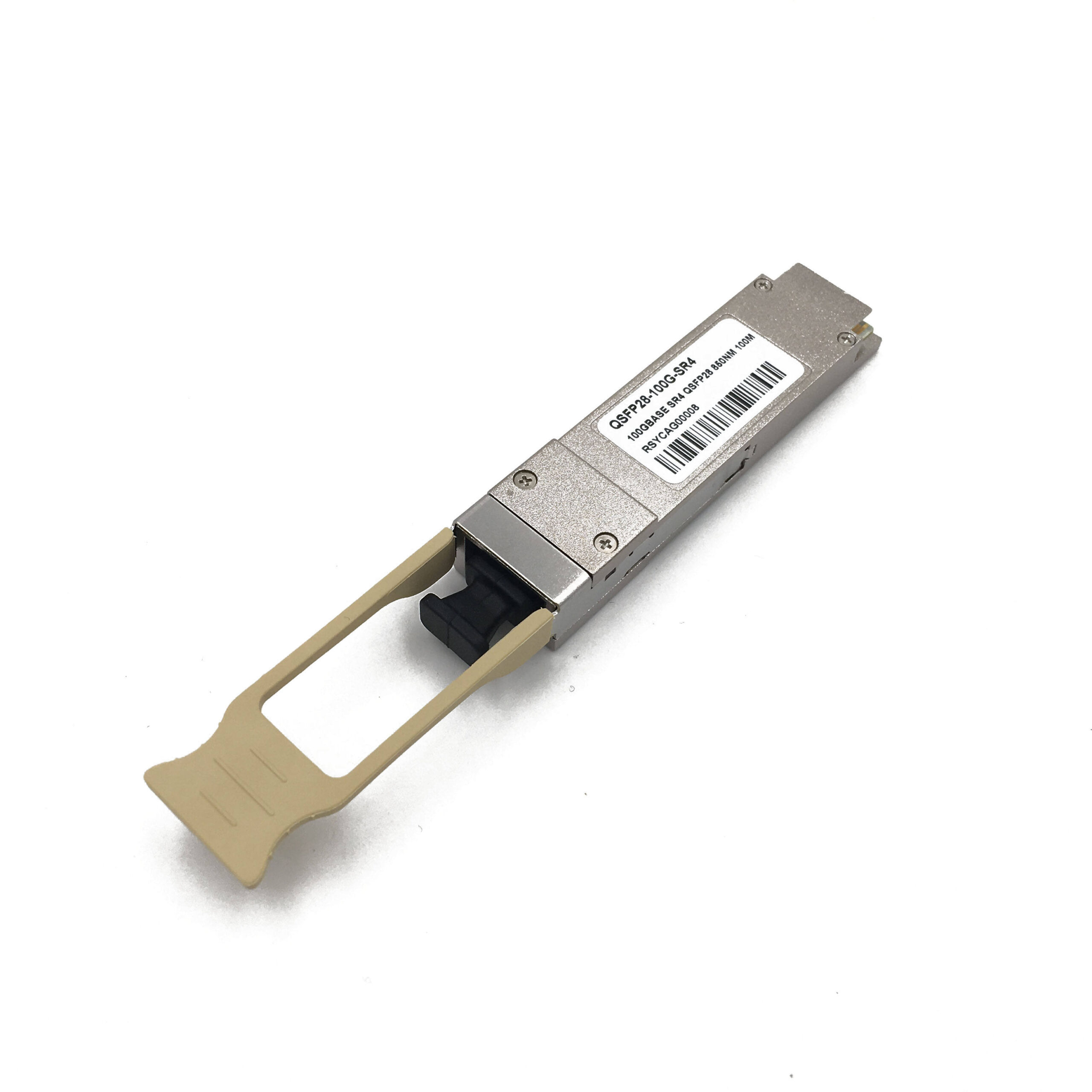
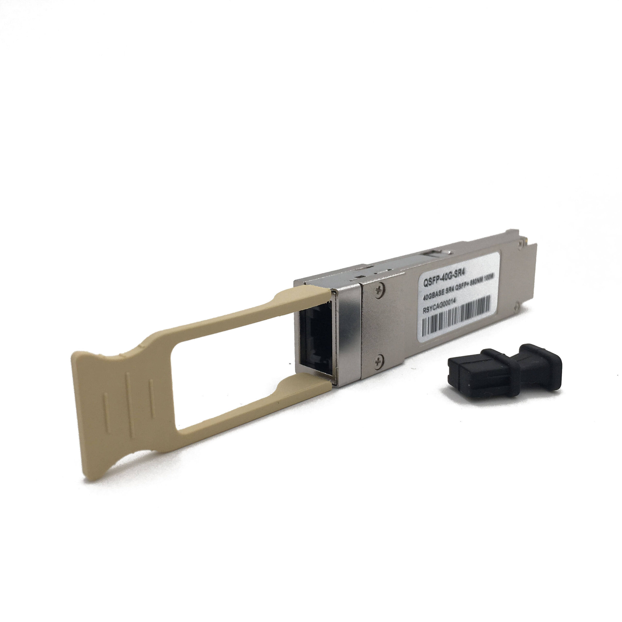
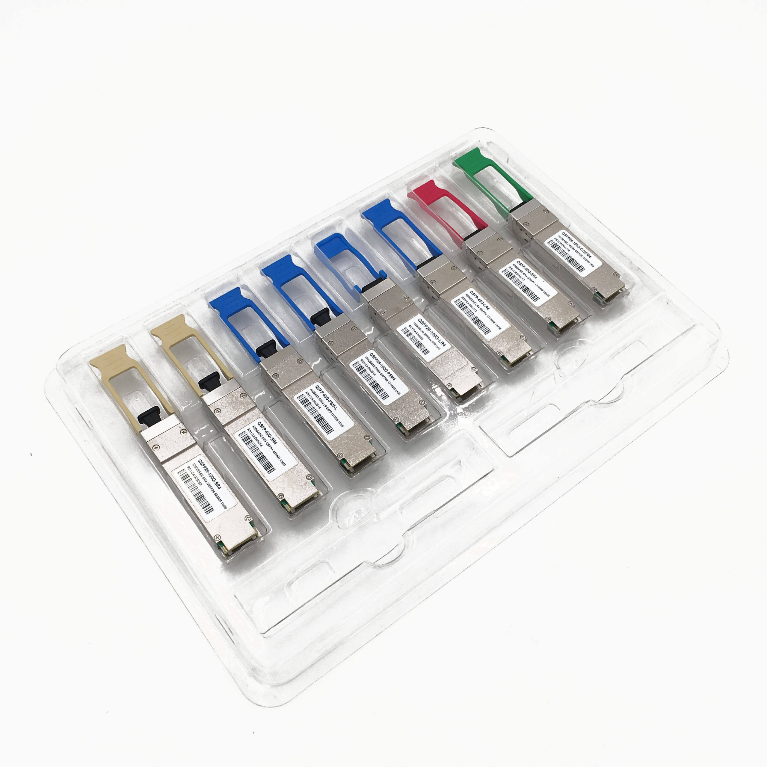
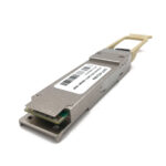
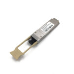
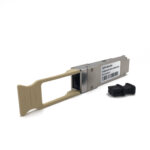
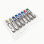
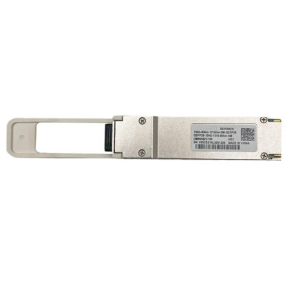
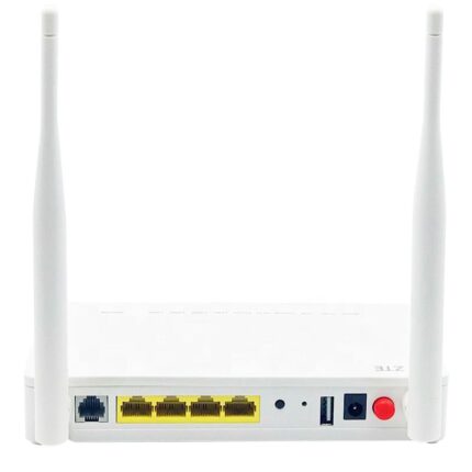
SEP 100G QSFP28 Description:
The SEP 100G QSFP28 Optical Transceiver Module is designed for use in 100GBASE Ethernet throughput up to 40km over single mode fiber (SMF) using a wavelength of 1310nm via duplex LC connector. It provides high-density and low-power 100GBASE Ethernet solution for data centers, high-performance computing networks, enterprise core and distribution layer applications. It is fully compliant with the QSFP28 MSA and IEEE 802.3ba 100GBASE-ER4 Lite standard.
Key Features:
- High-Speed Data Transmission: Supports data rates up to 103.125Gbps (4x 25.78Gbps), facilitating rapid data transfer in high-bandwidth networks.
- Long-Distance Connectivity: Offers reliable performance up to 100m over OM4 MMF, catering to various networking needs.
- Digital Diagnostics (DDM/DOM): Provides real-time monitoring of operating parameters via the I2C interface, ensuring efficient network management.
- Industrial Temperature Range: Operates reliably within a wide temperature range from -40 to 85°C (-40 to 185°F), making it suitable for diverse environments.
- Compact Form Factor: Utilizes a QSFP28 form factor, ensuring compatibility with QSFP28 ports and allowing for easy installation.
- Built-in Clock and Data Recovery (CDR): Features integrated TX & RX CDR for enhanced signal integrity and reliability.
- Comprehensive Protocol Support: Compliant with IEEE 802.3bm, QSFP28 MSA, SFF-8665, SFF-8636, RoHS, CPRI, and ECPRI protocols, ensuring interoperability and compliance with industry standards.
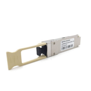
Product Parameters:
- Transmission data rate: 100g
- Max Data Rate: 103.1Gbps
- Operating case temperature: 0 ~ 70℃
- Power Consumption: 4.5W
- Application: FTTH FTTB FTTX Network
- Connector: LC
- Transmission Distance: 40KM
- Wavelength: 1296nm, 1300nm, 1305nm, 1310nm
Product Specifications of SEP 100G QSFP28:
Notice: When the long reach transceiver is used in short distance transmission, please matched with appropriate attenuator according to the table.
|
